4.2. 2-D Problems
4.2.1. Truss
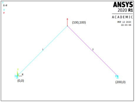
W2: A simple truss is shown below. Modulus for material is 200GPa, A=500mm2, force at node 2 in the +y direction of 1,000N. Find the displacements and stresses.
Data: E=2e5N/mm2, A=500mm2, F=1000N
Sol:
Preprocessing
- Change jobname
File> Change Jobname
Enter ‘Truss-1’, and click on ‘OK’.
- Define element types
Preprocessor> Element Type> Add/Edit/Delete
Click on ‘Add..’, highlight ‘Link’, then ‘3D finit stn 180’, click on ‘OK’, then ‘Close’.
- Define the cross sectional area for the Link180
Preprocessor> Sections> Link> Add
Type ‘1’ for ‘Add Link Section with ID’. Type ‘Truss 1’ for Section Name’. In this problem, the area is 500. Fill in the Link area value. Choose ‘Tension’ for ‘Tension Key and click on ‘OK’, then ‘Close’.
- Define Material Properties
Preprocessor> Material Properties> Constant> Isotropic
‘OK’ for material set number 1, then enter 2e5 for EX, then ‘OK’.
- Create nodes at truss joints
Preprocessor> Modeling> Create> Nodes> In Active CS
Enter 1 for node number Enter the location as (X,Y,Z)=(0,0,0). Click on ‘Apply’. Continue defining nodes 2&3 using the locations based on the sketch of the truss, but after entering the node 3 location, click on ‘OK’ instead of ‘Apply’. So, node 2 is at (X,Y)=(100,100) and node 3 is at (X,Y)=(200,0).
As a check to ensure all nodes were entered correctly, list the nodes.
Utility Menu> List> Nodes
Turn on node numbering.
Utility Menu> PlotCtrls> Numbering
- Create link elements between nodes
Preprocessor> Create> Elements> Auto Numbered> Thru Nodes
A picking menu appears. Pick node 1, then node 2, and click on ‘Apply’ in the Picking Menu. Pick node 2, then node 3, and click on ‘OK’ in the Picking Menu.
- Apply constraints and forces on the model.
Solution> Loads> Apply> Structural> Displacement> On Nodes
Pick nodes 1 & 3, then click ‘OK’ in the picking menu that has appeared. Choose ALL DOF, and use the default displacement value of zero.
Apply the forces.
Solution> Loads> Apply> Structural> Force/Moment> On Nodes
Pick node 2, then ‘OK’ in the picking menu, choose ‘FY’ as the direction of the force, and enter 1,000 for the force value. Click on ‘OK’.
Solution
- Solve the problem
Solution> Solve> Current LS
Click ‘OK’ in the ‘Solve Current Load Step’ Box.
Postprocessing
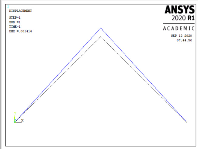
- Plot the deformed shape
General Postproc> Plot Results> Deformed Shape
Choose ‘Def + undeformed’, then ‘OK’.
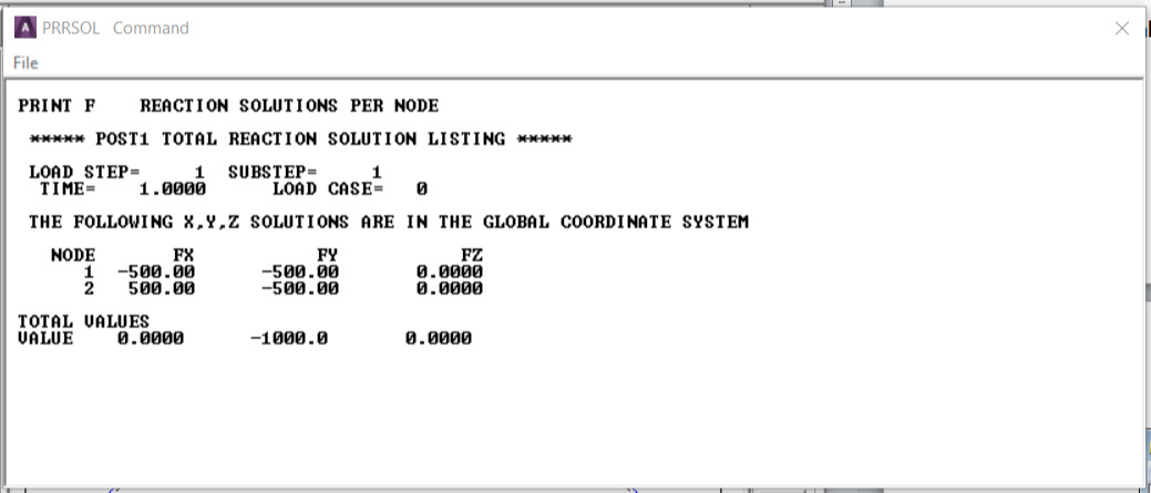
- List reaction forces
General Postproc> List Results> Reaction Solution
Click on ‘All struc forc F’, and ‘OK’.
Print the information in the Listing Box, by clicking, in that box, on File> Print. Or else, just write the information down.
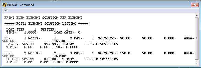
- List a summary, which includes the axial force and stress in each element
General Postproc> List Results> Element Solution> LineElem results> Structural ELEM
Click ‘OK’, and a summary for each element is printed, including the node numbers, from which the corresponding truss member can be identified, and also the axial force (MFORX), and the axial stress (SAXL). Record or print, this information.
- List the y direction deflections for each node.
General Postproc> List Results> Nodal Solution> DOF Solution> Y-Component of displacement
Click ‘OK’. Again, record or print, this information.
- Exit ANSYS
Quit> Save Everything> OK
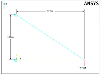
W3: Find the displacements and stresses in the truss shown below. Consider area=300mm2, E=200GPa.
Data: A=300mm2, E=2e5N/mm2, F=5,000N
Sol:
Preprocessing
- Change jobname
File > Change Jobname
Enter ‘Truss-2’, and click on ‘OK’.
- Define element types
Preprocessor > Element Type > Add/Edit/Delete
Click on ‘Add..’, highlight ‘Link’, then ‘3D finit stn 180’, click on ‘OK’, then ‘Close’.
- Define the real constants for the Link180, which are cross-sectional area and initial strain
Preprocessor> Real Constants> Add
Click ‘OK’ for ‘Type 1 LINK180’
In this problem, there is no initial strain (leave blank), and the area is 300. After filling in the area value, click on ‘OK’, then ‘Close’.
- Define Material Properties
Preprocessor> Material Properties> Material Models> Structural Linear> Elastic> Isotropic>
‘OK’ for material set number 1, then enter 2e5 for EX and ‘0.3’ for ‘PRXY’ , then ‘OK’.
- Create nodes at truss joints
Preprocessor> Modeling> Create> Nodes> In Active CS
Enter 1 for node number. Enter the location as (X,Y,Z)=(0,0,0). Click on ‘Apply’. Continue defining nodes 2&3 using the locations based on the sketch of the truss, but after entering the node 3 location, click on ‘OK’ instead of ‘Apply’. So, node 2 is at (X,Y)=(750,0) and node 3 is at (X,Y)=(0,500).
As a check to ensure all nodes were entered correctly, list the nodes
Utility Menu>List> Nodes
Turn on node numbering.
Utility Menu> PlotCtrls> Numbering
- Create link elements between nodes
Preprocessor> Create> Elements> Auto Numbered> Thru Nodes
A picking menu appears. Pick node 1, then node 2, and click on ‘Apply’ in the Picking Menu. Pick node 2, then node 3, and click on ‘OK’ in the Picking Menu.
- Apply constraints and forces on the model
Solution > Loads > Apply > Structural > Displacement > On Nodes
Pick nodes 1 & 3, then click ‘OK’ in the picking menu that has appeared.
Choose ALL DOF.
Apply the forces.
Solution> Loads> Apply> Structural> Force/Moment> On Nodes
Pick node 2, then ‘OK’ in the picking menu, choose ‘FY’ as the direction of the force, and enter -5000 for the force value. Click on ‘OK’.
Solution
- Solve the problem
Solution> Solve> Current LS
Click ‘OK’ in the ‘Solve Current Load Step’ Box.
Postprocessing
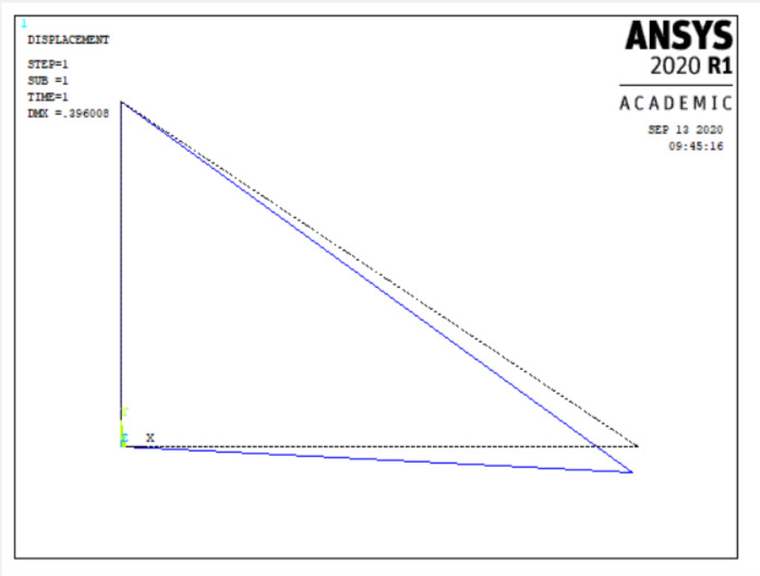
- Plot the deformed shape
General Postproc> Plot Results> Deformed Shape
Choose ‘Def + undeformed’, then ‘OK’.
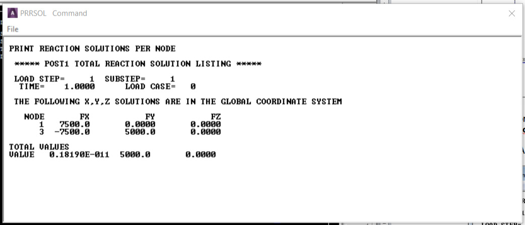
- List reaction forces
General Postproc> List Results> Reaction Solution
Click on ‘All items’, and ‘OK’.
Print the information in the Listing Box, by clicking, in that box, on ‘File > Print’. Or else, just write the information down.
- List a summary, which includes the axial force and stress in each element.
General Postproc> List Results> Element Solution> Favourites> Element Solution>
Click ‘OK’, and a summary for each element is printed, including the node numbers, from which the corresponding truss member can be identified, Record or print, this information.
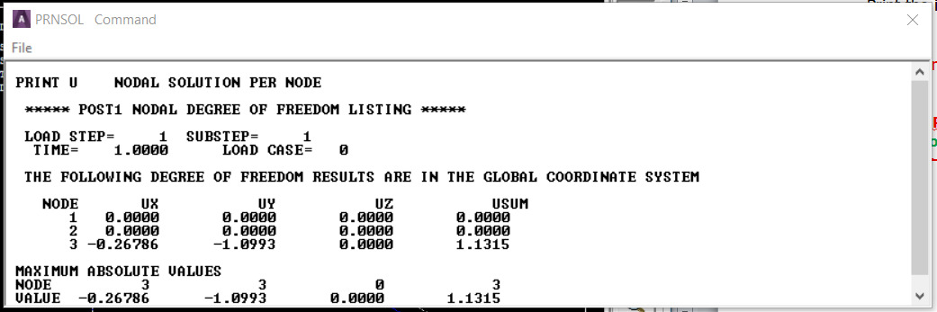
- List the x and y direction deflections for each node:
General Postproc> List Results> Nodal Solution> DOF Solution> Displacement vector sum
Click ‘OK’. Again, record or print, this information.
- Exit ANSYS
Quit> Save Everything> OK
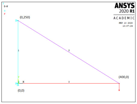
W4: Model and analyze the following simple truss structure geometry, loading, and boundary conditions. The model consists of three elements connected by three nodes. F=5,000N. Use ANSYS Link180 elements.
Data: A=300mm2, E=7e4, F=5,000N
Sol:
Preprocessing
- Change jobname
File> Change Jobname
Enter ‘Truss-3’, and click on ‘OK’.
- Define element types
Preprocessor> Element Type> Add/Edit/Delete
Click on ‘Add..’, highlight ‘Link’, then ‘3D finit stn 180’, click on ‘OK’, then ‘Close’.
- Define the sections for the Link180
Preprocessor> Sections > Link> Add
Enter unique section ID, say ‘1’ and Click ‘OK’ for ‘Add Link Selection’. Enter unique Section Name, say ‘A’
In this problem, and the area is 300. Fill in the area value, click on ‘OK’.
- Define Material Properties
Preprocessor> Material Properties> Constant> Isotropic
‘OK’ for material set number 1, then enter 7e4 for EX, then ‘OK’.
- Create nodes at truss joints
Preprocessor> Modeling> Create> Nodes> In Active CS
Enter 1 for node number (ANSYS would automatically number nodes if this column is left blank). Enter the location as (X,Y,Z)=(0,0,0). Click on ‘Apply’. Continue defining nodes 2&3 using the locations based on the sketch of the truss, but after entering the node 3 location, click on ‘OK’ instead of ‘Apply’. So, node 2 is at (X,Y)=(400,0) and node 3 is at (X,Y)=(0,250).
As a check to ensure all nodes were entered correctly, list the nodes:
Utility Menu> List> Nodes
Turn on node numbering.
Utility Menu> PlotCtrls> Numbering
- Create link elements between nodes
Preprocessor> Create> Elements> Auto Numbered> Thru Nodes
A picking menu appears. Pick node 1, then node 2, and click on ‘Apply’ in the Picking Menu. Next pick node 2, then node 3, and click on ‘Apply’ in the Picking Menu. Lastly pick node 3, then node 1, and click on ‘OK’ in the Picking Menu.
- Apply constraints and forces on the model
Solution> Loads> Apply> Structural> Displacement> On Nodes
Pick node 1, then click ‘OK’ in the picking menu that has appeared. Choose ALL DOF, and use the default displacement value of zero. Pick node 2, then click ‘OK’. Choose UX, and use the default displacement value of zero. Apply the forces.
Solution > Loads > Apply > Structural > Force/Moment > On Nodes
Pick node 2, then ‘OK’ in the picking menu, choose ‘FY’ as the direction of the force, and enter -5000 for the force value. Click on ‘OK’.
Solution
- Solve the problem
Solution> Solve> Current LS
Click ‘OK’ in the ‘Solve Current Load Step’ Box.
Postprocessing
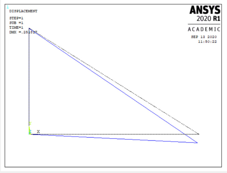
- Plot the deformed shape
General Postproc> Plot Results> Deformed Shape
Choose ‘Def + undeformed’, then ‘OK’.
- List reaction forces
General Postproc> List Results> Reaction Solution
Click on ‘All struc forc F’, and ‘OK’.
Print the information in the Listing Box, by clicking, in that box, on ‘File > Print’. Or else, just write the information down.
- List a summary, which includes the axial force and stress in each element
General Postproc> List Results> Element Solution> Favourites> Element Solution>
Click ‘OK’, and a summary for each element is printed, including the node numbers, from which the corresponding truss member can be identified,. Record or print, this information.
- List the x and y direction deflections for each node:
General Postproc> List Results> Nodal Solution> DOF Solution>
Click ‘OK’. Again, record or print, this information.
- Exit ANSYS
Quit> Save Everything> OK
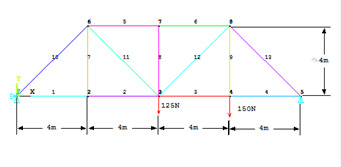
W5: Model and analyze the truss shown below. Cross-sectional area of truss members = 3.0E-4m2; Modulus of Elasticity = 207GPa.
Data: E=2.07e11N/m2, Area=3e-4m2
Sol:
Preprocessing
- Change jobname
File> Change Jobname
Enter ‘Bridge Truss’, and click on ‘OK’.
- Define element types
Preprocessor> Element Type> Add/Edit/Delete
Click on ‘Add..’, highlight ‘Link’, then ‘3D finit stn 180’, click on ‘OK’, then ‘Close’. Note that in ANSYS this element is sometimes referred to as ‘LINK 180’, because it is element type 180 in the ANSYS element library.
- Define the section for the
Preprocessor> Sections > Add
Enter area = 3e-4.
- Define Material Properties
Preprocessor> Material Properties> Constant> Isotropic
‘OK’ for material set number 1, then enter 2.07E11 for EX, then ‘OK’.
- Create nodes at truss joints
Preprocessor> Modeling> Create> Nodes> In Active CS
Enter 1 for node number. Enter the location as (X,Y,Z)=(0,0,0). Note that the locations are to be entered in meters, with node 1 located at the origin of the global x-y-z Cartesian coordinate system. Leave the entries for rotation angles blank. (Note: For this problem, all nodes will be in the X-Y plane, with Z=0). Click on ‘Apply’. Continue defining nodes 2-8 using the locations based on the sketch of the truss, but after entering the node 8 location, click on ‘OK’ instead of ‘Apply’. So, node 2 is at (X,Y)=(4,0), node 3 is at (X,Y)=(8,0), node 4 is at (X,Y)=(12,0), node 5 is at (X,Y)=(16,0), node 6 is at (X,Y)=(4,4), node 7 is at (X,Y)=(8,4), and node 8 is at (X,Y)=(12,4). The dimensions entered are in meters, and on the node definition menu, for this case, rotation angles are ignored, and for all nodes, Z=0.
As a check to ensure all nodes were entered correctly, list the nodes:
Utility Menu> List> Nodes
If any errors were made in defining the nodes, redefine a node by repeating the procedure of step 5. Of course, it is not necessary to redefine all nodes simply to move one. Just repeat the node creation command for the incorrectly placed node.
Turn on node numbering.
Utility Menu> PlotCtrls> Numbering
Check ‘Node Numbering’, then click ‘OK’. The node numbers may already be showing, but this will force the display of node numbers on subsequent plots.
- Create link elements between nodes.
Preprocessor> Create> Elements> Auto Numbered >Thru Nodes
A picking menu appears. Pick node 1, then node 2, and click on ‘Apply’ in the Picking Menu. Continue creating elements using the definitions listed in the table below. After picking the nodes for the last element (element 13), choose ‘OK’ (instead of ‘Apply’) to define the element and close the picking menu.
| Element | Node I | Node J |
|---|
| 1 | 1 | 2 |
| 2 | 2 | 3 |
| 3 | 3 | 4 |
| 4 | 4 | 5 |
| 5 | 6 | 7 |
| 6 | 7 | 8 |
| 7 | 6 | 2 |
| 8 | 3 | 7 |
| 9 | 4 | 8 |
| 10 | 1 | 6 |
| 11 | 6 | 3 |
| 12 | 3 | 8 |
| 13 | 5 | 8 |
- Apply constraints and forces on the model.
Solution> Loads> Apply> Structural> Displacement> On Nodes
Pick node 1, then click ‘OK’ in the picking menu that has appeared. Choose ALL DOF, and use the default displacement value of zero. Click on ‘Apply’. Pick node 5, then click ‘OK’ in the picking menu. To constrain this node in the Y-direction only, Click on ‘UY’. Make sure to unselect the ‘ALL DOF’ label! If the ‘ALL DOF’ label is highlighted, unselect it by clicking on it. After confirming that only ‘UY’ is highlighted, click ‘OK’.
Apply the forces.
Solution> Loads> Apply> Structural> Force/Moment> On Nodes
Pick node 4, then ‘OK’ in the picking menu, choose ‘FY’ as the direction of the force, and enter -150 for the force value. Click on ‘Apply’. Pick node 3, click ‘OK’ in the picking menu, and enter -125 for the force value (still in the FY direction). Click on ‘OK’.
Solution
- Solve the problem
Solution> Solve> Current LS
Click ‘OK’ in the ‘Solve Current Load Step’ Box.
Postprocessing
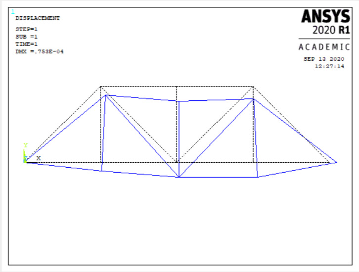
- Plot the deformed shape
General Postproc> Plot Results> Deformed Shape
Choose ‘Def + undeformed’, then ‘OK’.
- List reaction forces
General Postproc> List Results> Reaction Solution
Click on ‘All struc forc F’, and ‘OK’.
Print the information in the Listing Box, by clicking, in that box, on ‘File > Print’. Or else, just write the information down.
- List a summary, which includes the axial force and stress in each element:
General Postproc> List Results> Element Solution> Favourites> Element Solution>
Click ‘OK’, and a summary for each element is printed, including the node numbers, from which the corresponding truss member can be identified. Record or print, this information.
- List the x and y direction deflections for each node:
General Postproc> List Results> Nodal Solution> DOF Solution>
Click ‘OK’. Again, record or print, this information.
- Exit ANSYS
Quit> Save Everything> OK
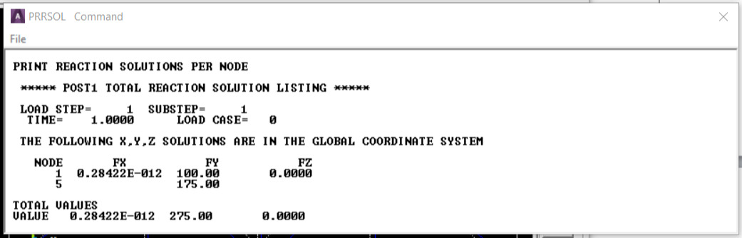
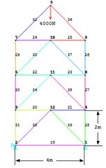
W6: A tower is made up of trusses. The four trusses at the top are each 2m in length. The cross section of each of the truss members is 6.25e-3sq.m. Assume the structure is made of steel with modulus of elasticity E=200GPa. The tower is constrained along X and Y directions at the bottom left corner, and along Y direction at the bottom right corner. The tower is loaded at the top. The load is in vertical direction only, and its magnitude is 4000N. Determine deflection at each joint. Determine stress in each member. Determine reaction forces at the base.
Data: Height of each truss=2m, cross sectional area=6.25e-3sq.m., E=2e11N/m2, Load=-4000N
Sol: A truss is a structural element that experiences loading only in the axial direction. In this example a 2-D Truss element will be used. A power transmission tower is a common example of a structure that is made up of only truss members. These towers are actually 3-D structures, but for the sake of simplicity a cross-sectional face of the tower will be taken. The tower is mainly subjected to loading in the vertical direction due to the weight of the cables. Also it is subjected to forces due to wind. In this example only loading due to the weight of the cables, which is in the vertical direction, will be considered.
Preprocessing
- Model the structure
Utility Menu> Workplane> WP Settings
The following window comes up
Check the Cartesian and Grid Only buttons
Enter Snap Incr=0.5, Spacing=0.5, Min=0, Max=10.
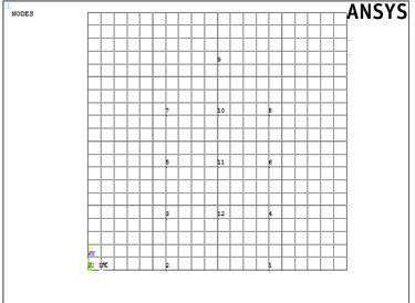
Main Menu> Preprocessor> Modeling> Create> Keypoints> On Working Plane
The following window comes up. Now pick the end points of the truss.
Select the keypoints on the workplane grid. The keypoints should look like this.
If the complete workplane cannot be seen then go to Utility Menu> PlotCntrls> Pan Zoom Rotate and zoom out to see the entire workplane
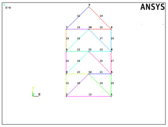
- Now create lines connecting the keypoints
Preprocessor> Modeling> Create> Lines> Lines> Straight Line
Create lines by picking keypoints to make the figure shown below
- Define material properties
Main Menu> Preprocessor> Material Props> Material Models
In the window that comes up, for Material Model 1, choose Structural> Linear> Elastic> Isotropic
Enter 1 for the Material Property Number and click ‘OK’. The following window comes up.
Fill in 2e11 for the Young's modulus and 0.3 for minor Poisson's Ratio. Click ‘OK’.
- Define element properties
Select element type.
Preprocessor> Element Type> Add/Edit/Delete...
In the 'Element Types' window that opens click on Add... The following window opens.
Type 1 in the Element type reference number
Click on Structural Link and select 3D finit stn. Click OK. Close the 'Element types' window.
So now Element type 1 is selected to be a structural Link180 element. The trusses will be modeled as elements of Type 1, i.e. structural link element.
- Now define the cross sectional area for this element.
Preprocessor> Real Constants
In the ‘Real Constants’ dialog box that comes up click on Add
In the ‘Element Type for Real Constants’ that comes up click ‘OK’. The following window comes up.
Type 6.25e-3 for cross sectional area and click on ‘OK’.
Now the cross sectional area of the link element is defined.
- Mesh the model
Divide the tower into elements
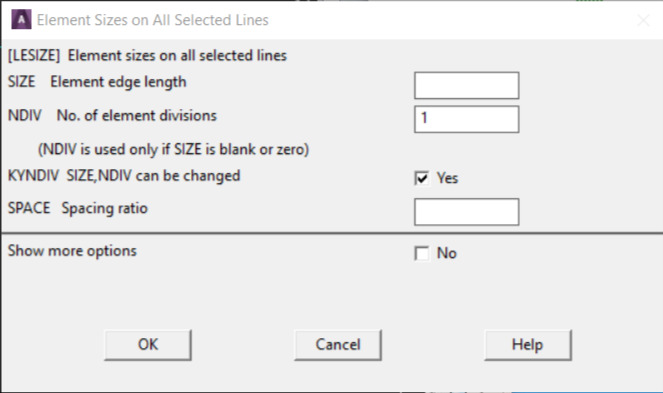
Preprocessor> Meshing> Size Cntrls> ManualSize> Lines> All Lines
In the menu that comes up type 1 in the field for 'Number of element divisions'.
This divides each of the lines in the figure into 1 element.
Click on ‘OK’. Now the figure is meshed, ANSYS will automatically divide each line into 1 element.
Preprocessor> Meshing> Mesh> lines
Select all the lines and click on OK in the ‘Mesh Lines’ dialog box.
Now each line is a truss element (Element 1).
- Define boundary conditions and constraints
Apply boundary conditions
The tower is constrained in the X and Y directions at the bottom left corner and in the Y direction at the bottom right corner.
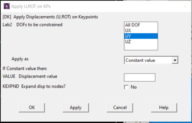
Main Menu> Preprocessor> Loads> Define Loads> Apply> Structural> Displacement> On Keypoints
Select the keypoint on displacement constraints are to be applied. The following window comes up.
Select UX and UY for the bottom left corner and UY for the bottom right corner and lick OK. The default displacement value is taken to be zero.
- Apply forces
Main Menu> Preprocessor> Loads> Define Loads> Apply> Structural> Forces/Moment> On Nodes
Select the top node.
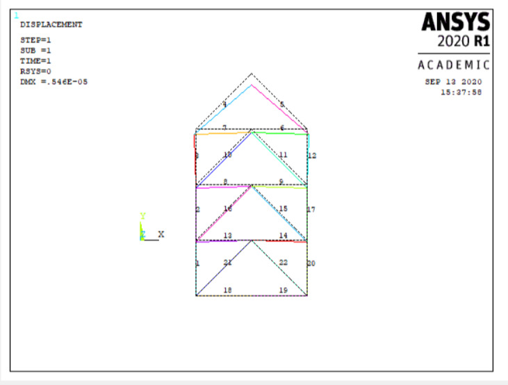
Click on OK in the 'Apply F/M on Nodes' window. The following window will appear. Select FY and enter 4000 as the Force/Moment value. Click on ‘OK’.
The figure on the ANSYS Graphics window will look like the following.
Solution
- Solve the problem.
Main Menu> Solution> Analysis Type> New Analysis
Select static and click on ‘OK’.
Solution> Solve> Current LS
Postprocessing
- List the results.
General Postproc> List Results> Nodal Solution
Select DOF solution and Displacement vector sum. Click on ‘OK’. The nodal displacements will be listed.
List the stresses for each element by clicking Gen Postproc > List Results > Element Solution.
Now select LineElem Results.