4.1. 1-D Problems
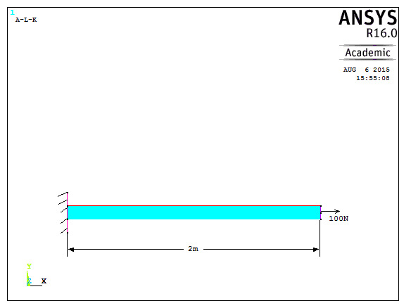
W1: Consider a 2m long steel bar of 50mm2 cross sectional area as shown below. Use two element mesh to model this problem. Find nodal displacements, element stresses and reaction. Take Young’s modulus, E=2x10⁵ N/mm2, load=100N.
Data: Length of bar=2000mm, Cross sectional area=50mm2, E=2x10⁵ N/mm2, Load=100N
Sol:
Preprocessing
- Change jobname
File> Change Jobname
Enter ‘Bar with end load’’ and click on ‘OK’.
- Define element types
Preprocessor> Element Type> Add/Edit/Delete
Click on ‘Add..’, highlight ‘Link’, then ‘3D finit stn 180’, click on ‘OK’, then ‘Close’.
- Define the cross sectional area for the Link180
Preprocessor> Sections> Link> Add
Type ‘1’ for ‘Add Link Section with ID’. Type ‘Bar’ for Section Name’. In this problem, the area is 50. Fill in the Link area value. Choose ‘Tension’ for ‘Tension Key and click on ‘OK’, then ‘Close’.
- Define Material Properties
Preprocessor> Material Properties> Material Models> Structural> Linear> Elastic> Isotropic
‘OK’ for material set number 1, then enter 2e5 for EX, then ‘OK’.
- Create nodes at bar nodes
Preprocessor> Modeling> Create> Nodes> In Active CS
Enter 1 for node number (ANSYS would automatically number nodes if this column is left blank). Enter the location as (X,Y,Z)=(0,0,0). Click on ‘Apply’. Continue defining nodes 2 & 3 using the locations based on the sketch of the bar, but after entering the node 3 location, click on ‘OK’ instead of ‘Apply’. So, node 2 is at (X,Y,Z)=(1000,0,0) and node 3 is at (X,Y,Z)=(2000,0,0).
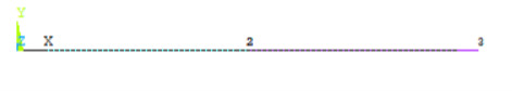
As a check to ensure all nodes were entered correctly, list the nodes.
Utility Menu> List> Nodes
Turn on node numbering.
Utility Menu> PlotCtrls> Numbering
- Create link elements between nodes
Preprocessor> Modelling> Create> Elements> Auto Numbered> Thru Nodes
A picking menu appears. Pick node 1, then node 2 and click on ‘Apply’ in the Picking Menu. Pick node 2, then node 3 and click on ‘OK’ in the Picking Menu.
- Apply constraints and forces on the model.
Solution> Loads> Apply> Structural> Displacement> On Nodes
Pick node 1, then click ‘OK’ in the picking menu that has appeared. Choose ‘ALL DOF’ and use the default displacement value of zero.
Apply the forces.
Solution> Loads> Apply> Structural> Force/Moment> On Nodes
Pick node 3, then ‘OK’ in the picking menu, choose ‘FX’ as the direction of the force, and enter 100 for the force value. Click on ‘OK’.
Solution
- Solve the problem
Solution> Solve> Current LS
Click ‘OK’ in the ‘Solve Current Load Step’ Box
Postprocessing
- Plot the deformed shape
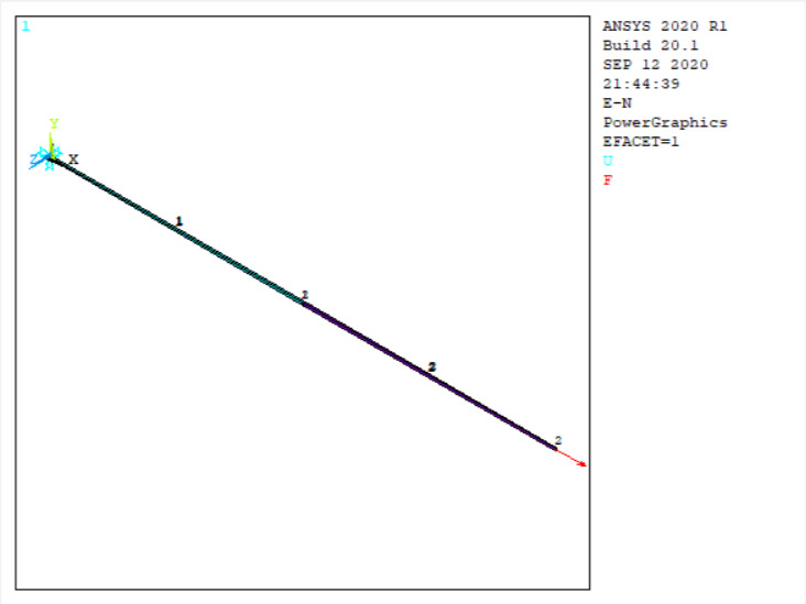
General Postproc> Plot Results> Deformed Shape
Choose ‘Def + undeformed’, then ‘OK’
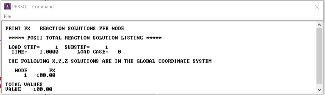
- List reaction forces
General Postproc> List Results> Reaction Solution
Click on ‘All struc forc F’, and ‘OK’
Print the information in the Listing Box, by clicking, in that box, on File> Print. Or else, just write the information down.
- List a summary, which includes the axial force and stress in each element
General Postproc> List Results> Element Solution> LineElem results> Structural ELEM
Click ‘OK’, and a summary for each element is printed, including the node numbers, from which the corresponding bar element can be identified, and also the axial force (MFORX), and the axial stress (SAXL). Record or print, this information.
- List the x and y direction deflections for each node.
General Postproc> List Results> Nodal Solution> DOF Solution> ALL DOFs
Click ‘OK’. Again, record or print, this information.
- Exit ANSYS
Quit> Save Everything> OK